Compared with general optical distance measurement technology, laser distance measurement technology offers advantages such as convenient operation, simple system structure, and operability both day and night. In contrast to radar distance measurement, it features excellent anti-interference performance, high precision, and strong resistance to electromagnetic interference. The superiority of laser distance measurement becomes more pronounced when the detection distance is long.
Laser distance measurement technology refers to a distance-measuring technique that calculates the distance to a target using laser pulses or continuous-wave laser beams emitted toward the target. The commonly used laser distance measurement methods include the triangulation method, pulse method, phase-shift method, and interference method.
1. Triangulation Laser Distance Measurement
The measuring method of a laser displacement sensor is called the laser triangulation reflection method. A laser distance meter has a fixed precision—for the same meter, the precision remains consistent whether measuring 10 meters or 100 meters. However, the measurement precision of the laser triangulation reflection method is related to the measuring range: the larger the range, the lower the precision.
It is a high-precision non-contact sensor that performs position and displacement measurements based on the laser triangulation principle and echo analysis principle. It is widely used in industrial measurement of geometric quantities such as position, displacement, thickness, radius, shape, vibration, and distance.
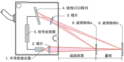
Figure 1 Schematic Diagram of Laser Triangulation Measurement
A semiconductor laser (1) is focused onto the measured object (6) via a lens (2). The reflected light is collected by a lens (3) and projected onto a CCD array (4); a signal processor (5) calculates the distance to the object by using trigonometric functions based on the position of the light spot on the array (4).
The laser emitter projects visible red laser light onto the surface of the object through a lens. The laser light reflected by the object passes through the receiver lens and is received by the internal CCD linear camera. Depending on the distance, the CCD linear camera can “see” this light spot at different angles. Using this angle and the known distance between the laser and the camera, the digital signal processor can calculate the distance between the sensor and the measured object.
Meanwhile, the position of the light beam on the receiving element is processed through analog and digital circuits, and the microprocessor analyzes the data to compute the corresponding output value. Within the analog quantity window set by the user, a standard data signal is output proportionally. If a switching output is used, it is turned on within the set window and turned off outside the window. In addition, independent detection windows can be set for analog and switching outputs. This method is commonly used in applications such as railway tracks, product thickness, flatness, and dimensional measurement.
2. Pulse Method Laser Distance Measurement
The process of pulse method distance measurement is as follows: The laser emitted by the distance meter is reflected by the measured object and then received by the meter, which simultaneously records the round-trip time of the laser. Half the product of the speed of light and the round-trip time is the distance between the distance meter and the measured object.
The measurement precision of the pulse method is generally around ±1 meter. In addition, the measurement blind zone of such distance meters is usually about 15 meters. With the development of optoelectronic technology, the precision is constantly improving, and the blind zone is continuously narrowing. This method is mainly used in topographic surveying, tactical forward edge distance measurement, missile trajectory tracking, laser radar distance measurement, and distance measurement between artificial satellites and the Earth-Moon system.
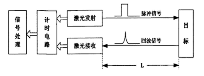
Figure 2 :Schematic Diagram of Pulse Method Measurement
Its principle is that the laser emission system sends out an ultra-short-duration pulse laser. After traveling the distance to be measured (L), the laser is reflected by the target object. The emitted pulse laser signal is received by the photodetector in the laser receiving system. A time interval circuit calculates the time (t) between the emission of the laser and the arrival of the echo signal, and then derives the distance (L) between the target object and the emitter. Its precision depends on: the rising edge of the laser pulse, the bandwidth of the receiving channel, the signal-to-noise ratio of the detector, and the accuracy of the time interval.
3. Phase-Shift Laser Distance Meter
A phase-shift laser distance meter modulates the amplitude of a laser beam using a radio frequency. It measures the phase delay generated when the modulated light travels round-trip along the measurement line once, and then converts the distance represented by this phase delay based on the wavelength of the modulated light. In other words, it indirectly measures the time required for the light to travel round-trip along the measurement line, as shown in Figure 3.
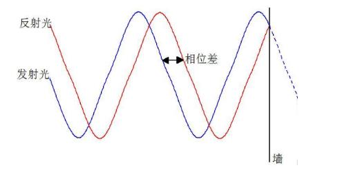
Figure 3:Schematic Diagram of Phase-Shift Laser Distance Measurement
In the figure, the blue line represents the emitted light, and the red line represents the reflected light. It can be clearly seen that when the emitted light hits a wall and is reflected, the waveform of the reflected light is essentially a mirror image of the waveform that would exist without the wall. Therefore, the magnitude of the phase difference has no relation to the speed of light, but is related to when the emitted light encounters an obstacle.
Phase-shift laser distance meters are generally used in high-precision distance measurement. Due to their high precision (typically at the millimeter level), to effectively receive reflected signals and limit the measured target to a specific point that matches the instrument’s precision, all such distance meters are equipped with reflectors called “cooperative targets”.
4. Interference Method Laser Distance Measurement
The interference method for distance measurement is a technique that uses various interferometers to measure distance based on the principle of light wave interference. The advent of lasers has expanded the application scope of the interference distance measurement method. The basic principle of laser interference distance measurement is shown in Figure 4 .
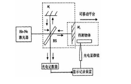
Figure 4 :Schematic Diagram of Interference Method Measurement
The light emitted by a laser is split into two beams by a beam splitter. One beam is directed to the fixed reference arm of the interferometer and returns after hitting the reference mirror (M1) to form a reference beam; the other beam is sent to the measurement arm of the interferometer. The mirror (M2) in the measurement arm moves with the displacement of the measured object, and this beam returns from the measurement mirror to form a measurement beam. The measurement beam and the reference beam overlap and interfere with each other to form an interference signal.
The number of light-dark changes in the interference signal directly corresponds to the displacement of the measurement mirror, which can be expressed by the formula: L = Nλ/2 (where L is the displacement, N is the number of light-dark changes, and λ is the wavelength of the laser). Therefore, starting from the initial counting point of N set by the photoelectric microscope, the measured displacement (L) can be obtained by counting N.